Fort Payne Roadcuts Near Celina, Tennessee
Introduction and General Summary
SUBMARINE CHANNELS IN THE MISSISSIPPIAN (Osagean) FT. PAYNE FORMATION, CLAY COUNTY, TENNESSEE
Frank W. Stapor, Jr., Emeritus Professor
fstapor@tntech.edu
Dept. of Earth Sciences
Tennessee Technological University
PO Box 5062, Cookeville, TN 38501
INTRODUCTION:
The recently relocated highway TN 52 in eastern Clay County contains a number of 15- to 25-meter high, 100- to 300-meter long, vertical, roadcuts through the Mississippian Ft. Payne Formation. The siliciclastic mudstone facies of the Ft. Payne is spectacularly exposed in these roadcuts, Figs 1 and 2. The eastern roadcuts, which are in the upper 20- to 30-meters of the Ft. Payne, contain submarine channels filled with siliciclastic mudstone and crinoid/bryozoan grainstones. These channels have up to 10-meters of erosional relief. Overlying these channel-fills are a number of 1- to 3-meter thick, sheet-like, crinoid/bryozoan grainstones (locally dolomitized) that can be traced for up to a kilometer or more along the roadcuts of highway TN 52. In several roadcuts the depositional facies change or pinch-out of the channel-filling, grainstone, sediment gravity flows into carbonate-rich siliciclastic mudstone can be observed in detail. A similar channel-fill occurs in roadcuts through the upper Ft. Payne Formation on TN53 north of Celina, TN., Fig. 1.
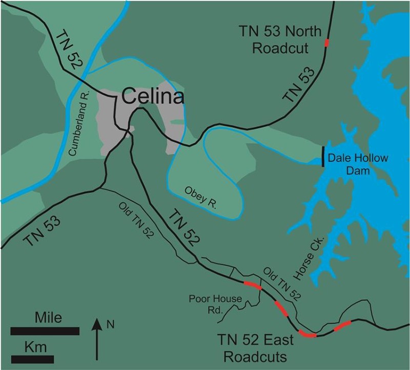
Figure 1. General location map of the Ft. Payne Formation submarine channel-fills exposed along highways TN52 and TN53.
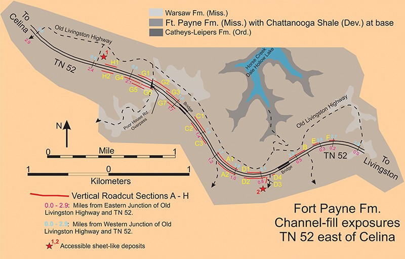
Figure 2. Detailed location map for the Ft. Payne Formation roadcuts on TN52 east of Celina, TN that expose submarine channel-fills and/or sheet-like bodies.
Photo-mosaics of the roadcuts which exhibit channel-fills and/or sheet-like deposits were made in order to record and thus preserve this unique stratigraphic data set. Multiple, overlapping, 35mm digital images were taken of each roadcut and then merged into a single photo-mosaic in Adobe Photoshop. Images were taken at a horizontal spacing of approximately 5-meters. Unavoidable distortion exists at the upper and lower margins of each merged photo-mosaic. The resulting photo-mosaics show in great detail bedding surfaces as well as variations in color and texture that reflect different lithologies. In addition, facies lithologies were documented by polished slabs and thin sections.
The bedding surfaces interpreted in the crinoid grainstones of these photo-mosaics are typically stylolites (Fig. 3A) which mimic the orientations of the internal structures, however, actual laminations of crinoid grains can be observed on weathered exposures (Fig. 3B).
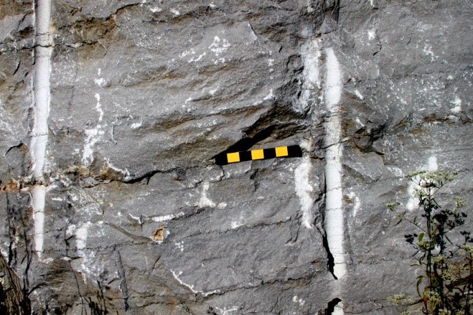
Fig. 3A. Roadcut exposure of crinoid grainstone with parallel, planar stylolites that are interpreted as representing the orientations and planarity of the internal structures. Scale divisions are 5 cm; image is of Section A1 Northwest Panel.
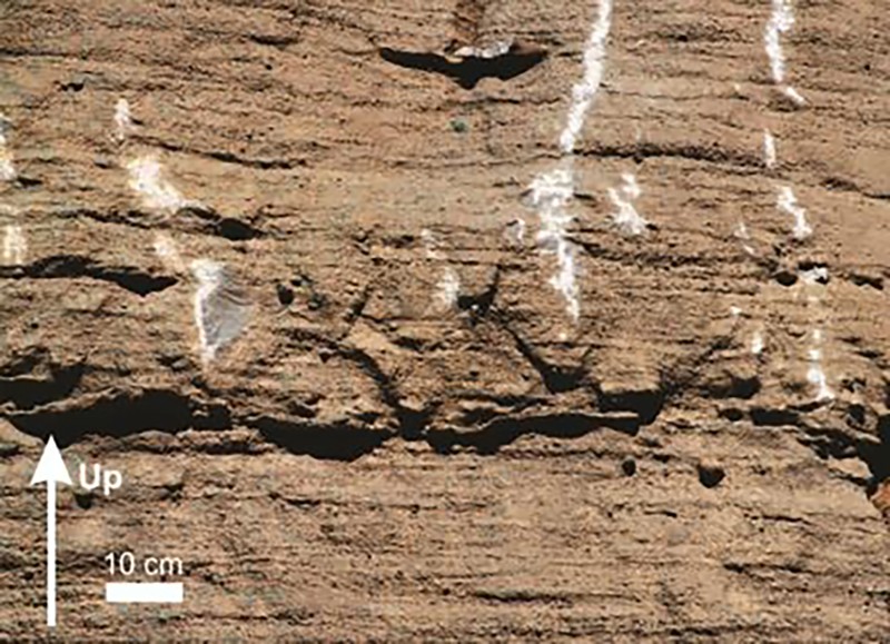
Fig. 3B. Planar lamination in crinoid grainstone exposed in weathered surface at Section B.
In terms of volumetric importance, the primary lithology present in these channel-fills is dark to light gray, siliciclastic mudstone containing varying amounts of dispersed crinoid grains (Fig. 4A); siliceous sponge spicules and secondary dolomite rhombs are visible in thin sections. The secondary lithology, however the more obvious, is crinoid grainstone that also contains variable amounts of Fenestrate sp. bryozoan fragments and rare Productid sp. brachiopod shells (Fig. 4B).
The sheet-like deposits that overlie the channel-fills are exposed near the tops of the TN52 roadcuts and are essentially inaccessible for direct observation. However, they are accessible along two side roads, the Red Stars labeled 1 and 2, Fig. 2. These sheet-like units consist primarily of crinoid-rich, pack-/wackestone, Figure 5.
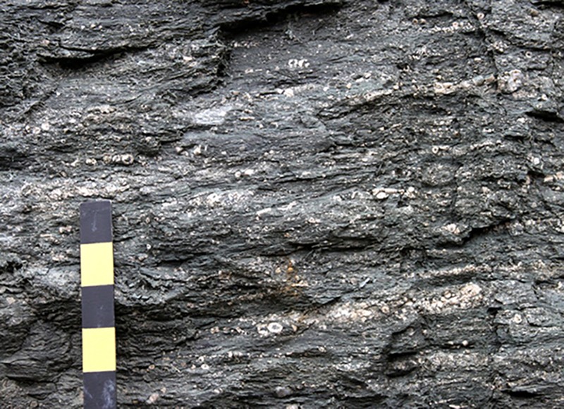
Figure 4A. Roadcut exposure of the siliciclastic mudstone with dispersed crinoid grains facies, Section D1. The scale divisions are 5 cm.
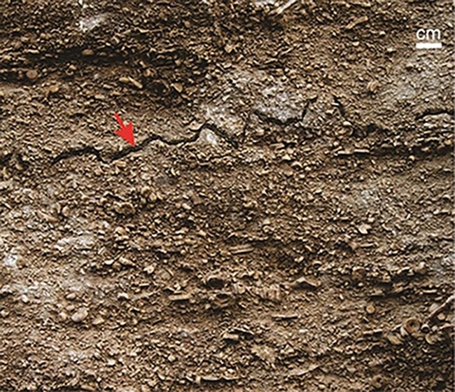
Figure 4B. Weathered exposure of crinoid grainstone. The red arrow marks a stylolite that is essentially parallel to the faint planar lamination, Section A1 Middle Panel.
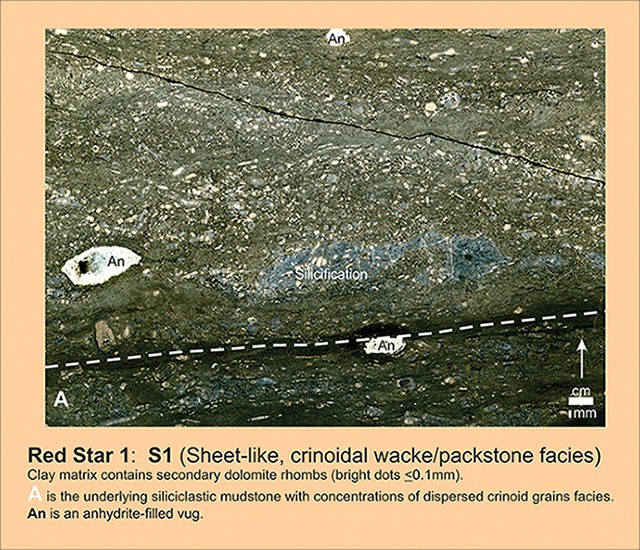
Figure 5. Polished slab of sheet-like deposit of pack-/wackestone that contains siliciclastic mudstone matrix. Skeletal grains include crinoids and brachiopods; the sorting is very poor (Sample S1 from side road at Red Star 1 locality in Fig. 2). The white dashed-line marks the contact between the sheet-like unit and the underlying siliclastic mudstone.
General Summary
Because most of the major channel-fills have roadcut exposures on both sides of TN52 it is possible to estimate their local orientations. Using this strategy all of the major channel-fills have a local E-W orientation, Fig. 3. The Ft. Payne siliciclastic mudstone facies present in the Celina, TN, region, as well as adjacent parts of Tennessee and Kentucky, represents the basinward or distal deposits of a westward prograding, late Osagean delta, the shoreline of which was oriented NW-SE (Peterson and Kepferle (1970), Kepferle (1977), Lewis and Potter (1978), and Ausich and Meyer (1990)). Thus, the regional Ft. Payne paleogeography argues that east to west transport deposited these TN52 channel-fills located immediately east of Celina, TN.
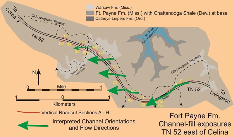
Figure 3. Channel orientations and flow directions for channel-fills along TN52 east of Celina, TN. All of these channels exposed along this part of TN52 most likely had a generally E-W orientation, based on the alignments of the steeply inclined margins. Regional Ft. Payne paleogeography strongly suggests westerly flow rather than easterly.
The channel-fill depositional model shown in Figure 4 attempts to explain: 1) the origin of the inclined, planar, parallel bedded crinoid grainstone and its position adjacent to a relatively steep, eroded margin, and 2) the origin of the “massive” to thickly bedded, siliciclastic mudstone with dispersed crinoid grains that appears to blanket and/or onlap? the adjacent crinoid grainstone. The initial channels were steep-margined, broad, and flat-bottomed; the maximum measured aspect ratio is 170:1, which is itself a minimum because the opposite channel margin was not exposed. Sediment gravity flows of various types, high density turbidity and debris, are hypothesized to be primarily responsible for the deposition of these channel-fills. However, the crinoid-grainstone clinoforms are hypothesized to have been deposited by a sediment gravity flow that had a pronounced cross-channel energy gradient, highest near the steeply inclined margin and then decreasing towards the remaining part of the channel, Fig. 4: Panels 3, 4, 8, and 9. At the downdip end of each grainstone clinoform (bedset?) there is a facies change to siliciclastic mudstone. Typically these facies change intervals can be confidently recognized only over thicknesses of several decimeters, however, the entire 3-meter thickness of Channel-fill B in Sections G3, G4, G5, and G5 includes the facies change from grainstone to mudstone.
The siliciclastic mudstones that blanket and\\or onlap the crinoid-grainstone clinoforms are hypothesized to have been deposited by sediment gravity flows that had minimal, if any, cross-channel variation in energy and resulted in a widespread, blanket-like deposit, Fig. 4: Panels 5, 6, 10, and 11; the observed onlap geometries may well be the products of subsequent erosion of the more channel-margin portion of pre-existing siliciclastic mudstone blankets. The blanket-like, siliciclastic mudstones are the vast majority of these channel-fills. The various bounding disconformities that occur at the base of each clinoform, crinoid-grainstone depositional episode can only be confidently identified where there is a pronounced lithologic difference between over- and underlying units. These critical disconformities are invisible where siliciclastic mudstone overlies siliciclastic mudstone, and that situation characterized essentially most, perhaps 90% or more, of these channel-fills.
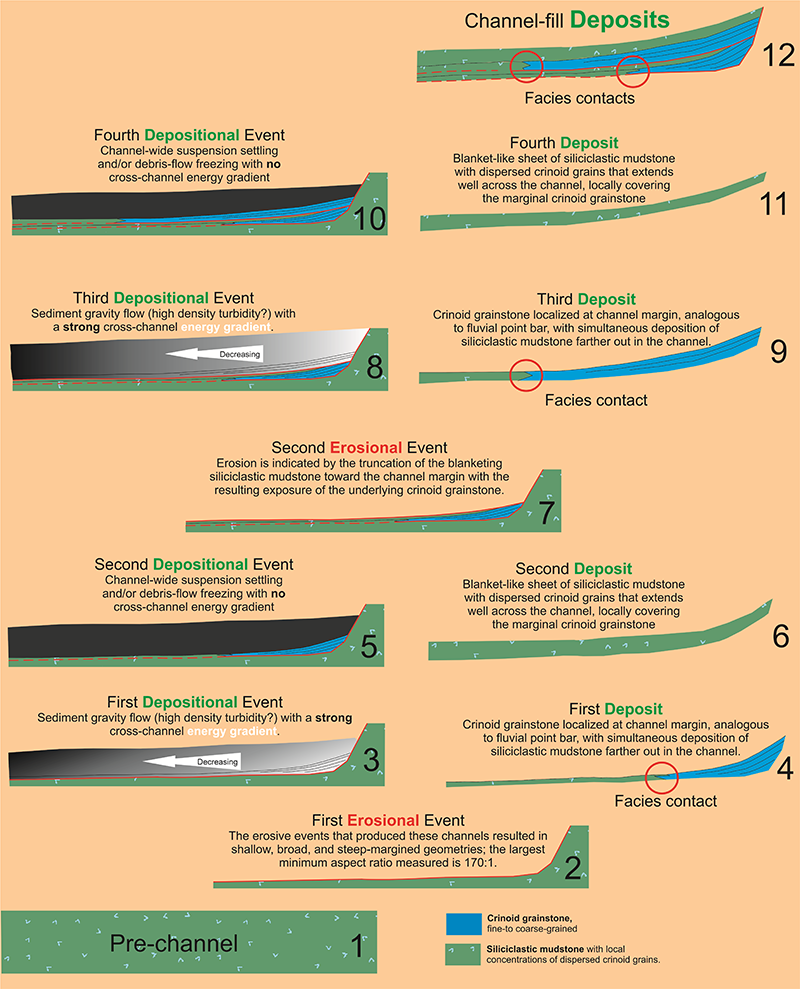
Figure 4. Deposition Model. These channel-fills were primarily deposited from various sediment gravity flows. Crinoid grainstone was deposited by the higher energy portion of a flow that had a strong cross-channel gradient.
It should be kept in mind that the bulk of the material in these channel-fills is siliciclastic mudstone with dispersed crinoid grains; the crinoid and bryozoan grainstones are a very small percentage of the total channel-fill. Thus, the source of the channel-filling material may well have been a slope break on a siliciclastic mud-rich shelf and the grainstone bodies the result of cross-channel, hydrodynamic sorting in meandering submarine channel in a process analogous to the deposition of quartz sand in a fluvial point bar.
References
Ausich, W. I. and Meyer, D. L., 1990, Origin and composition of carbonate buildups and associated facies in the Fort Payne Formation (Lower Mississippian, south-central Kentucky): an integrated sedimentologic and paleoecologic analysis: Geol. Soc. of American Bulletin, v. 102, p. 129-146.
Kepferle, R. C., 1977, Stratigraphy, petrology, and depositional environment of the Kenwood Siltstone Member of the Borden Formation (Mississippian), Kentucky and Indiana: U. S. Geol. Survey Professional Paper 1007, 49p.
Lewis, R. Q., Sr. and Potter, P. E., 1978, Surface rocks in the western Lake Cumberland area, Clinton, Russell, and Wayne Counties, Kentucky: Geological Society of Kentucky, Geological Survey of Kentucky, Annual Field Conference, 41p.
Peterson, W. L. and Kepferle, R. C., 1970, Deltaic deposits of the Borden Formation in central Kentucky: U. S. Geol. Survey Professional Paper 700-D, p. 49-54.